How Dielectric Constant Affects PCB
What Is Dielectric Constant
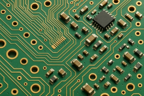
The dielectric constant, also represented by Dk or εr, is a value that expresses the ability of a material to hold electrical energy in an electric field. It is an inherent property of insulating materials and directly affects how signals propagate in printed circuit boards (PCBs). In simple terms, the dielectric constant determines how a PCB material will impact signal velocity, impedance, and overall performance.
Dielectric Constant of PCB Materials
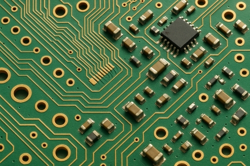
PCB materials have a wide variation in dielectric properties. Standard FR-4, which is the most common PCB substrate, has a 4.0–4.8 dielectric constant, depending on the vendor and process. Some other high-performance substrates, such as Rogers laminates or PTFE-based substrates, have dielectric constants as low as 2.2–3.0.
The choice of PCB material and dielectric constant depends on the application. The standard FR-4 will suffice for general-purpose or low-frequency electronics. For RF (radio frequency) or microwave PCBs, or high-speed digital circuits, however, low-dielectric-constant materials are preferable as they reduce signal delay and loss.
Further reading: PCB Base Materials: Types and Properties
How Dielectric Constant Impacts PCB
The dielectric constant directly impacts some of the most important parameters of PCB performance:
1.Signal Propagation Speed: The speed of a signal through a PCB trace is inversely proportional to the square root of the dielectric constant. The higher the Dk material, the more it slows down the signal propagation, and the lower the Dk material, the faster the signal transmission. This becomes a critical factor in high-speed circuits where timing and synchronization are vital.
2. Impedance Control: Controlled impedance traces are essential in high-frequency PCBs. The dielectric constant of the material establishes the capacitance between the trace and the reference plane, which determines the characteristic impedance. Small variations in Dk can result in impedance mismatch, resulting in reflections, signal loss, or electromagnetic interference (EMI).
3. Signal Integrity: A consistent dielectric constant across the PCB material ensures minimal distortion of high-frequency signals. Variations in Dk may introduce jitter, crosstalk, and signal attenuation, degrading communication and digital circuit reliability.
4. Crosstalk and Capacitance: The dielectric constant affects parasitic capacitance between traces. A higher Dk increases capacitance, which can lead to greater crosstalk between adjacent traces. Designers should cautiously balance trace spacing, layer stacking, and material selection to negate these effects.
Considerations and Warning for PCB Designers
Engineers should consider the dielectric constant while designing PCBs to get the optimum results:
• Material Selection: Choose substrate materials with a dielectric constant suitable for the application frequency range. For RF and high-speed circuits, low-Dk materials are favored, while for low-speed or general-purpose boards, normal FR-4 is sufficient.
• Consistency: Ensure the dielectric constant is consistent throughout the PCB and from batch to batch in production. Manufacturers' specifications must be verified, particularly for demanding high-frequency applications.
• Temperature and Moisture Effects: Dielectric constant can be a function of temperature and moisture absorption. Designers need to consider the operating environment and choose materials whose Dk is stable under expected conditions.
• Stack-Up Design: Layer thickness and trace width, in combination with the dielectric constant, affect impedance. Stack-up design and simulation need to be carefully done to meet impedance targets and maintain signal integrity.
• Testing and Validation: Use impedance analyzers and high-frequency testing to validate the PCB design specifications are achieved. Material selection or layer configuration may need to be tuned to optimize performance.
Conclusion
The dielectric constant is a significant parameter with a high influence on PCB performance. It affects signal speed, impedance, capacitance, and signal integrity in general. For more information, please check Stanford Electronics.
Frequently Asked Questions
Q1: What is a good dielectric constant for high-speed PCBs?
A low dielectric constant between 2.2 and 3.5 is preferred for RF or high-speed PCBs for faster signal propagation and reduced signal loss.
Q2: Does the dielectric constant play a role in PCB power loss?
Yes. Dielectric constants, when they are higher, can result in higher parasitic capacitance, which results in more signal loss, especially at higher frequencies.
Q3: How does temperature affect the dielectric constant?
Dielectric constant can vary with temperature. High-frequency application materials usually have a stable Dk over a wide temperature range.
Q4: Can FR-4 be used for RF applications?
FR-4 is okay for low-frequency or general use, but its relatively high and unstable dielectric constant make it less appropriate for high-frequency RF circuits.
Q5: How do PCB designers manage Dk variations?
Designers can use materials of stable dielectric constants, verify manufacturers' specifications, and simulate impedance and signal propagation to minimize variations.

